Hello all,
I’ve had a productive day and finished the code that sets up the serial communications. I’ve implemented this as a menu only accessible at power up, by holding the mode and Z buttons. The pictures below show all of the screens that the controller uses together with (hopefully) a short video showing the controller in action. Apologies for the slightly blurred pictures but I don’t have a tripod and using the flash on the camera is a non starter.
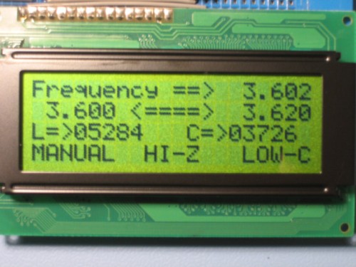
This is the main screen and shows the controller in automatic mode. In this case the radio frequency is 3.602MHz and the controller is showing that the current L and C values will be used from 3.600MHz to 3.620MHz. Low impedance matching is selected and the capacitor in the balanced L network is switched to the low range position.
This picture shows the controller in manual mode and high impedance matching has been selected.
Here, you can see that the radio frequency (3.810MHz) is outside of the amateur band so the tuner will not attempt to set the L and C values. I’ve done this to keep the number of memories high within the amateur bands so that antennas with a high Q can be used without a problem.
This is the main setup menu with 2 options – set up the serial communications to the radio or clear all of the L and C settings from the tuner (this will usually only be used once on first power up).
This is the communications setup menu, again with 2 options to either change the baud rate or switch between master and slave modes. Slave mode will be useful if you are using a computer with the radio and wan’t to “snoop” the serial port with a Y cable.
Fairly self explanatory, currently supports 4800 or 38400 baud but others could be added.
Screen to select master or slave mode for the serial port.
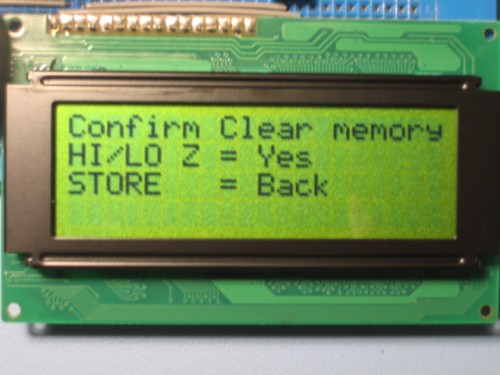
This is the only setup screen that will ask for confirmation as it cannot be undone. As the tuner may take quite a while to initially set up I thought it wise to get confirmation that the memories really do need clearing.
The video clip below should show the controller in operation:
The noise you can hear in the background of the video clip is the stepper motors moving. I need to start boxing the controller up now and sort out the RF end of the tuner.
73 Paul.


Fantastic work! do visit my blog too…….
By: Sai, VU2SGW on February 5, 2009
at 7:05 am